Prototype Testing
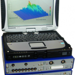
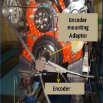
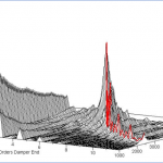
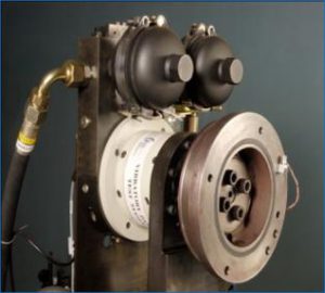
Natural Frequency Test
- Servo Hydraulic Vibratory Damper Test System
- Precision system with controlled rotary actuator through servo hydraulic system.
- Damper Hub is mounted on rotary actuator and represents the actual mounting condition.
- Rotary actuator is excited through a servo value with known excitations.
- Two accelerometers are mounted in phase, one on actuator and the other on Damper inertia ring. Which in turn acts as closed loop circuit.
- The excitations exerted by the actuator are captured by the accelerometers.
- As the ring is separated through elastomeric member there is a difference in phase between the excitations of two sensors.
- At resonance the difference in phase is exactly 90 deg. Which determines the Natural frequency of the damper.
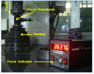
Axial Pull Test
- Damper is mounted onto the fixture.
- A force transducer is placed onto the damper.
- A precisely controlled press is used to find out the axial force & the adhesive strength of the damper.
- An indicator is connected to transducer and the maximum value is displayed.
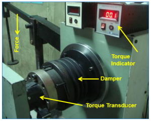
Slip Torque Test
- Torque applied under static condition on the damper elastic member by fixing either inertia ring or hub & gradually displacing the other to measure the Torsional bonding strength of the rubber element under assembly.
- Damper Hub is mounted onto torque lever.
- Damper Ring is fixed onto the torque transducer.
- Torque is applied gradually onto the damper hub.
- The amount of torque exerted is indicated by an indicator.
- Sudden drop in the torque reading indicates slip between hub & ring.
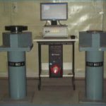
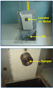
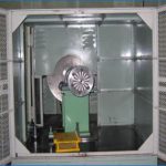
Burst Testing
- Damper is mounted onto locator through a motor.
- Damper is run at 2.5 times the rated RPM of engine for 2 minutes.
- Test is carried out to find out the structural integrity of the cast part and bond integrity of elastomer and the metal parts.
- Shift in correlation mark is checked before and after test.
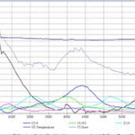
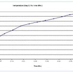
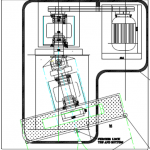
Hooke’s Joint Test
- Viscous damper is excited on Hooke’s joint with angular excitation.
- Temperature rise of the damper casing is measured.
- Temperature rise should be linearly or gradual rise with respect to time.
| Hooke’s Angle | Angular Displacement |
| 10 ° | 0.438 ° |
| 11 ° | 0.531 ° |
| 12 ° | 0.633 ° |
| 13 ° | 0.744 ° |
| 14 ° | 0.864 ° |
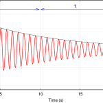
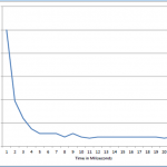
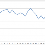
Torsio Test Rig
- Damper mounted on rig and excited manually.
- Decay in the amplitude level of the given excitation is monitored.
- If decay in amplitude level observed, damper is functionally acceptable.
- If damper ring is seized no decay in amplitude level is observed.